
Understanding Rectifiers the Simple Way
by Editor - Jan-11-2026
From our college days, many of us carry a certain confusion in our minds when we hear terms like Rectifier, Converter, Inverter, AC to DC, DC to DC, and AC to AC.
Instead of bringing clarity, these words often feel overwhelming. But in reality, the core idea behind many of these concepts is quite simple.
In this blog, let’s forget complex circuits and equations for a moment and understand a basic rectifier using a very simple, hands-on experiment.
The components we use :
To explain a rectifier, we only need three basic components:
A step-down transformer (230V AC to 6V AC).
A mini DC motor.
A single diode.
That’s it. No bridge rectifier, no filter capacitors—just the basics.
Step 1: AC Supply from the Transformer
When we power the transformer using an AC mains supply, the secondary side gives us a 6V AC output. This AC voltage continuously changes its direction.
Now, let’s directly connect this 6V AC output to the mini motor.
What happens?
The motor does not rotate continuously.
Instead, it produces a vibration or shaking effect.
Why?
Because AC current changes direction rapidly, the motor keeps trying to rotate in one direction and then the opposite direction. Since these changes happen very fast, the motor cannot maintain continuous rotation.
Step 2: Adding a Single Diode
Now, disconnect one wire from the motor.
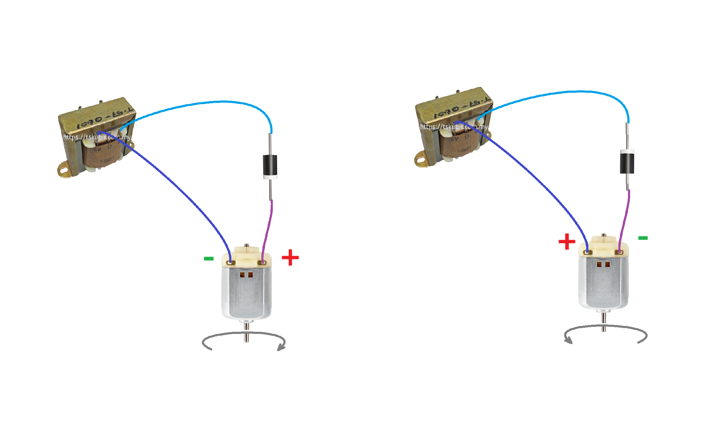
Insert a diode in series between the transformer and the motor.
Connect the other end of the diode back to the motor.Power the circuit again.
What happens now?
The motor starts rotating continuously.
What changed?
The diode allows current to flow in *only one direction*. This means:
Only one half-cycle of the AC waveform reaches the motor.
The other half-cycle is blocked.
In simple terms, the AC supply is now converted into a pulsating DC.
👉 This is the basic working of a rectifier.
Step 3: Reversing the Diode
Now comes the interesting part.
Remove the diode.
Invert it (reverse its direction).
Connect it back into the circuit.
Power the circuit again.
What do you observe?
The motor still rotates, but in the opposite direction.
What does this mean?
By reversing the diode:
You are now allowing the other half-cycle of the AC waveform to pass.
The polarity of the resulting DC is reversed.
So effectively:
First diode connection: AC → DC (one polarity)
Second diode connection: AC → DC (opposite polarity)
What Did We Actually Learn?
With this simple experiment, we understood three important concepts:
1. AC to DC conversion can be done using just a single diode (half-wave rectifier).
2. A motor connected directly to AC will vibrate, not rotate smoothly.
3. Reversing the diode reverses the *polarity of the DC output*.
This is why we say:
A rectifier converts AC into DC.
Even though the DC here is not smooth, it is sufficient to demonstrate the concept clearly.
Clearing the Bigger Confusion
Now let’s simplify those confusing terms:
Rectifier: Converts AC to DC.
Inverter: Converts DC to AC.
DC to DC Converter: Changes DC voltage level.
AC to AC Converter: Changes AC voltage or frequency.
All complex power electronics systems are built on these simple core ideas.
Final Thoughts
You don’t always need complex circuits to understand electronics. Sometimes, a transformer, a diode, and a small motor are more than enough to make concepts crystal clear.
(Refer to the attached images for circuit connections and motor direction.)

Embedded Basics
Understanding microcontrollers.
IoT Systems
Connecting devices intelligently.
RTOS Explained
Real-time operating systems.

PCB Layout Tips
Clean and efficient board design.
Signal Integrity
Reducing noise and EMI.
Multilayer Boards
High-speed PCB design.